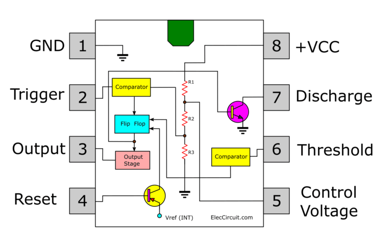

In the end, you should see your LED blinking like this: Finally, power up your circuit by connecting the battery to your breadboard: You can either follow the previous schematic or follow the breadboard wiring diagram below. You can use the preceding links or go directly to /tools to find all the parts for your projects at the best price! So, we just need to add an LED to the output of the previous circuit. In this section, you will flash an LED using the 555 timer in astable mode. With the output voltage that comes from pin 3, you can control anything you want (like an LED, speaker, motor, etc.). The frequency can be calculated using the following expression: The frequency of the oscillation can be adjusted by changing the values of the resistors R1 and R2 and the capacitance of the capacitor C. To make the 555 timer work in astable mode, you should wire your circuit like this: EN555 circuit diagram – astable mode Voltage output versus time in astable mode Astable mode The voltage is high, then low, then high, then low again and so on (this is called astable mode). In a circuit diagram, usually the 555 timer is drawn as follows: EN555 represented in a schematic diagram Output This is a document with a lot of information, but what you really need to pay attention right now is to the pinout. If you search on Google 555 timer datasheet, one of the first results should be a PDF datasheet. In this post, you’ll see an example in astable mode. Bistable mode: the 555 timer changes its output depending on the state of two inputs.Astable mode: outputs an oscillating pulse signal.Monostable mode: usually used to create time delays.The 555 timer can operate in three different modes: These series of pulses allow you to continuously blink an LED, for example. The EN555 is usually used to generate continuous series of pulses. The 555 timer is an integrated circuit, it is extremely versatile and can be used to build lots of different circuits. You’ll explore what it is, the three different modes and its pinout. In this blog post, we will introduce the 555 Timer Integrated Circuit (IC).


 0 kommentar(er)
